 |
||||||||||||
| Home |
|
Products For Sale |
FAQs, Tips, Manuals |
Referral List |
|
Photo Gallery |
|
Links |
|
Contact Us |
|
|
|||||||||||||||||
CRT tube area Yoke interconnect board: Ampro changed the way that you change the deflection of the tubes to be set for floor/ceiling/front or back mounting. On the yoke interconnect board there are two small PC boards that plug into the main board. Pull out these boards, flip them over and you change the deflection scan. There is one board for V deflection and one for H deflection. Note that the mating PC board connectors that these small boards plug into have a plastic piece mounted in place to prevent the boards from being plugged in incorrectly. Once in a blue moon these plastic spacers fall out and the boards can be incorrectly inserted. It is also very easy to knock one of the connectors loose when changing the deflection boards on this yoke board. You will usually get an ‘open interlock’ message on the remote if a connector gets loose on this board when you try and power up. It is also easy to loosen a focus or convergence board connector that goes to the tubes when working in this area. If you lose the focus or convergence control to one tube, check to make sure all connectors are seated properly. Late model Ampro sets have full shielding over the tube necks (not shown here). The tubes and neck assemblies are the same, they are just harder to get to when there are metal shields over the whole neck of the tube.
|
|
||||||||||||||||
© Copyright CurtPalme.com. All Rights Reserved. |

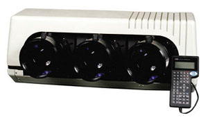
 Ampro 3600/4600