Definitive CRT Projector Setup Guide |
(Page 1)
|
Page:
1 2
3 4
5 6
|
| |
Here, humbly is a guide for first time projector owners to get the most out
of their projector. Hey, veteran CRT owners might get something out of this too!
Feel free to critique like crazy if I’m missing some steps (quite possible) and
email me with comments. I’ve based this on the NEC XG, but of course the
principles can be applied to any CRT projector, entry level or high end, ES or
EM focusing.
The following topic are described in detail with plenty of pictures showing
you exactly what to adjust:
- Raster/tube face setup
- Optical focusing
- Scheimpflug adjustments
- Electronic focusing
- Astigmatism control
- Lens toe-in
- Electronic astig
adjustment
- Electronic focus
- Tilt
- Geometry
- Bow
- Amplitude
- Linearity
- Linearity balance
controls
- Keystone
- Pin-cushion
- Point adjustment
- Later model point
convergence software
Raster/tube face setup
This is one of the most misunderstood areas of CRT projector setup. Here’s
some basics:
All CRT tubes come in a 4:3 format rather than a 16:9 configuration.
Regardless of whether you project in a 4:3 format or a widescreen one, you want
to use as much of the tube face as possible to maximize tube life. By using as
much of the tube face as possible, you’ll also increase the maximum resolution
out of the tube as you’re spreading the image out over a larger area of the tube
face.
Note that the internal test pattern of the projector will always be slightly
larger than the projected image. This is purposely done so that the test pattern
will overshoot the screen slightly. By overshooting the screen, you’ll be
ensured perfect convergence right to the edge of the screen and past it. When
the projected image then fills the screen, it will be perfectly converged.
The idea is to maximize the phosphor area of the tube without overshooting
the tube face. There is cooling fluid between the glass face that you see on the
tube and the actual phosphor behind it. If you overshoot the tube face, you’re
causing the electron beam to shoot off the phosphor onto the edge of the glass
that has no cooling fluid on it, and the tube edge can overheat and implode.
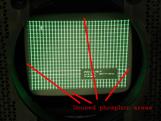
Shown below are some good and bad examples of tube phosphor use.
Good- the raster/test pattern is centered on the tube face, there is a
visible margin between the edge of the tube and the test pattern. Maximum use is
made of the tube face.

In a 16:9 (widescreen) configuration, less of the phosphor face is used, as
the picture will be projected in widescreen mode as shown below. While the below
image shows the test pattern being very close to the tube edges, the projected
video image will be smaller (less width and height), so a margin of safety is
still being used in this setup. Since you’re (hopefully) not going to be
projecting the test pattern for hours upon hours, there’s no chance of a tube
implosion with the test pattern running right to the edge of the tube in setup
mode.

The NEC manual is somewhat flawed in that it tells you to mount the projector
back a little more than what is ideal for maximum tube face use. The picture
below shows a test pattern with a wide margin between the edge of the pattern
and the edge of the tube. You’ll end up using less phosphor area which will
result in shortened tube life and lower overall resolution.

You also want the test pattern centered on the face of the tube. Below are
examples of rasters/test patterns that are shifted off center on the tube face.
This will result in convergence drift and uneven tube wear.
Image shifted too far to the right on the tube face:

Image shifted too far up on the tube face and to the left:

The NEC XG chassis specifically has two sets of raster shift adjustments. The
fine adjustment is the ‘position’ button on the remote. The coarse adjustments
are done in the ‘ref adjust’ settings in the ‘adjust’ mode. The ‘raster
centering’ mode will allow you to perfectly center the test pattern on each
tube. While adjusting the ‘ref adjust’, make sure the ‘position’ settings are at
0,0. This will then allow you to fine tune the raster shift during the final
adjustments while maintaining the overall centering of the coarse ‘ref adjust’
settings.
The height and width controls of the set will adjust how much of the tube
face you’re using with both the test pattern and the video image. You’ll run out
of width before you run out of height on the tube face, so maximize the width
used without overshooting the tube face. The exact height can be dialed in
during the geometry setup of the green tube.
Once your raster is centered on each tube, you can now check your throw
distance to the screen. I normally recommend that you set your projector on the
floor before mounting it to the ceiling if that’s where the projector will be
located. By temporarily floor mounting the set, you can move the projector back
and forth a few inches to adjust the throw distance, then measure your throw
distance and mark the ceiling appropriately to mount the bracket.
Typically I recommend that the test pattern overshoots the screen left to
right by about 2-3” on each side. The actual video image should then fill the
screen, and the width/amplitude control of the set should be able to compensate
for slight adjustments needed to fill the screen.
Focusing
There are two distinct parts to focusing a CRT projector: The optical
focusing, which is the relationship of the lens to the tube face and the screen,
and the electronic focusing of the electron beam/image on the tube face. Both
the optical and electronic focusing must be set perfectly in order to get a
sharply focused image on the screen.
Optical Focusing
Most projectors have lenses similar to the ones on the NEC. Each lens has two
adjustments to optically focus the tubes, the back wingnut or knob that is the
coarse/overall focusing, and the front adjustment that is for corner focusing
only.

Loosen the back wingnut and grasp the front barrel of the lens to rotate the
lens. Set the lens for the best focusing in the middle of the screen and tighten
the wingnut. Then loosen the front wingnut and again rotate the front barrel
Tighten the wingnut once the corner focus is set.
Here is a picture of the coarse optical focus misadjusted. The whole screen
is out of focus. If you put on sunglasses and look through the lens at the tube
face, it should be in focus.

Here’s a picture of the corner focus wingnut being out of adjustment. Note
that the center of the image is in focus, but the edges are blurry.

Scheimpflug adjustments
Some projectors (including the NEC XG series have an adjustment for altering
the physical relationship between the tube face and the back of the lens. By
having the ability to slightly adjust the position of the lens to the tube face,
corner focusing can be improved upon. The NEC manual has a chart of what
positions the plastic levers to set Scheimpflug should be at depending on your
screen size. For the most part, the chart is accurate, however if a tube is set
slightly cockeyed in it’s metal mounting frame, these tabs might need to be
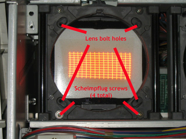
played with a bit. To adjust the Scheimpflug tabs, refer to the below picture:

With the lens still in place, loosen the lend bolts a few turns, but don’t
take them out completely. Also loosen the Scheimpflug screws (one in each
corner) a few turns, but again, don’t take them out completely.
With the 8 screws loose, the plastic tabs on the top of the lens frame should
move side to side, and referring to the Scheimpflug settings in the NEC manual,
set the tabs to their correct positions. Re-tighten each of the screws.
If you find the top and bottom or side to side focus to be off slightly, feel
free to play with the positions of the plastic tabs to perfect the mechanical
focusing. The Scheimpflug and lens focusing do somewhat interact, so you might
need to readjust the lens focusing once the Scheimpflug has been reset.
Electronic Focusing
The second and equally important adjustment for focusing is the electronic
tube focusing of the electron beam on the face of the tube. The NEC XG sets has
9 zones of electronic focusing along with 9 zones of astigmatism adjustment,
found in the ‘ref adjust’ menu.
HINT: For best focusing, set the contrast control to 100%. This will push the
tube harder and by setting the contrast to 100, the focus setting will improve
even more once you set the contrast back down to 75% (factory default). Since
you’re not leaving the set at 100% contrast for long, there’s no risk of
damaging the tubes.
Start with the middle of the screen. Ramp the focus control up and down to
get optimum focusing in the middle of the screen. Ideally this setting should be
between -10 and 0. If you find that the best focusing is outside of this range,
then adjust the focus trimpots found under the top cover of the projector on the
card cage. These are the master focus trimpots that adjust the range of focusing
of the controls within the remote.
Once the center focus has been adjusted, move to the top, bottom, side and
corner settings. These edge controls have a lot less range and will affect the
image a lot less than the center focusing. The ‘H’ test pattern works really
well for setting the optimum focusing of the XG. A properly focused NEC
projector will have a well focused H pattern all over the screen as shown below:

And a close-up:

Astigmatism control
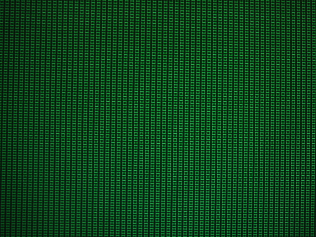
The NEC XG sets also have 9 zones of astigmatism. The clever engineers at NEC
automatically put the set into defocused mode with the fine dot pattern
displayed. Adjust each astig zone so that the defocused dots look round and
aren’t oval shaped. Once you exit the astig mode, the set will be in focus
again. Again, the astig and focus controls do slightly interact, so you might
need to retweak the focus controls. (Hey, don’t whine, I once watched Guy Kuo,
CRT setup master, spend 3 hours on just getting JUST the green tube focused
100%.)

|


