The procedure below is provided by RogerH of our forum. Thank you Roger! Questions? See the
original forum
thread.
I just finished with what seems to be a successful CRT wear-evening process
intended to extend the usable area of a lightly worn XG green tube (one of two
Runco XG-852s). I know that this has been done before, but I wasn't able to find
much hard information in my searches prior to trying it. I thought I would
document the various steps for anyone else that may want to give it a try. This
turned out to be a lot easier and much more controllable than expected.
The idea (which has apparently been around a long time) is to wear down and
blend virgin phosphor areas surrounding existing undersized or misplaced CRT
wear patterns. This is done to allow subsequent use of a larger image area
without any visible discontinuities where the original wear area meets the new
larger area.
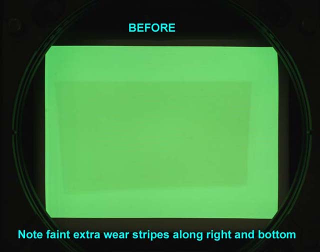
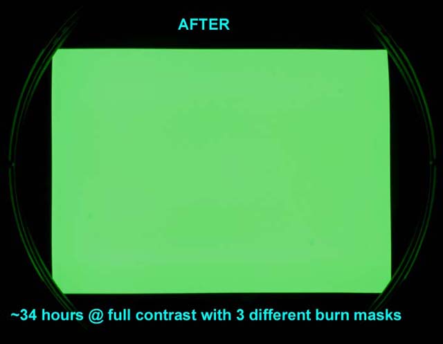
Here are the before and after images of my CRT face after my experiment.
Ignore the slight moire in the before picture-it was still sharply focused when
the photo was taken. And obviously the "after" image should really be the same
brightness of the center of the "before" picture - I didn't do any post
processing.


The steps written here are based on the use of my older version of Photoshop
6.0, but if you have a newer version you should be able to translate without any
problem.
This procedure was performed on one of a pair of projectors that had
apparently been run side-by-side for about 1300 hours. The projector setup had
not been optimized, and the wear zones were undersized and poorly centered on
both axes. The horizontal offset of each projector from the screen center also
required settings that resulted in some vertical keystone distortion in the wear
pattern.
The projectors could have been run as-is by operating within the trapezoidal
wear zone, but this would have severely under-utilized the phosphor area of all
three tubes. And since the R and B tubes are almost mint, this was unacceptable.
Although there were many suggestions to just replace the CRT, these projectors
were bought as parts machines for my good 852, and CRT replacement wasn't going
to happen.
Besides, the end result was far more satisfying and educational.
Creating the Burn Mask Outline
One of the projectors had a straightforward single wear area, but projector B
had been repositioned at least a couple times throughout its life, as indicated
by multiple overlapping wear patterns. This one would require multiple burn
steps to balance the wear, so I decided to do the hardest one first.
Since I would only be working on the green tube, the first step was to create
a 640 x 480 rectangle in Photoshop with a solid background of R=0, G=255, and
B=0. This was burned to a DVD. There would have been nothing wrong with creating
a white burn mask, but I knew I would sometimes forget to mute the R and B
tubes, so I decided to make it foolproof.
A DVD player was run through a scaler to increase the number of horizontal
lines to the point that electrical defocusing would merge the lines and prevent
line burn. I used 1024 x 768, but I did not defocus the projector just yet.
This DVD was then played and a new input memory (appropriately named "burn")
was set up to display the filled rectangle as large as possible on the screen.
Keystone was set as needed near 0 to display a rectangle on the CRT, not on a
projected image. Even with the width and height controls set to 100%, the area
was not as large as it could be, so VR5301 on the H-Def board was set slightly
out of spec to increase the image width. I set the width to approximately the
same width as the internal test patterns, which was about 4-6 mm from the edge
of the tube face. Since I would be using the internal all-white test pattern
throughout the procedure for reference, the left and right blanking were set to
keep the now-larger test pattern from running off the CRT face with any
significant energy.
At this point the alignment and raster centering controls were set to make
the rectangle as large and as perfectly shaped and centered as possible. It was
important to also use a grid pattern to check linearity and lin-balance, because
nonlinearity that is not visible on the filled green rectangle would have
resulted in uneven wear.
Once the rectangle was centered, shaped, and linear, the settings were saved
to memory. A copy of the memory was made, and any subsequent minor adjustments
were made to the copy. The green rectangle displayed on the CRT face was then
photographed under a low contrast setting using a long shutter time (to avoid
scan-banding), low ISO, and in my case, a neutral density filter to help cut the
light down. You need to be able to see all of the details of any wear pattern(s)
without being washed out by too much light. The camera also needed to be set up
as perpendicular and centered as possible on the CRT face to minimize
distortion.
The camera image was opened in Photoshop. I grabbed the rectangular selection
tool and changed the style to "CONSTRAINED ASPECT RATIO" and entered the numbers
of 640 x 480. A selection box was drawn around the illuminated area of the CRT
(making sure that nothing was cut off). The image had some distortion which was
later corrected. The selection was cropped to eliminate the areas outside the
selection. Next, the image was resized from the 640 x 480 (ratio) image to an
actual 640 x 480 pixels. EDIT>TRANSFORM>DISTORT was then used to stretch or
distort the image as needed to fill the 640 x 480 area with the illuminated
image. There was some lens/setup distortion, so the image had some pincushion
that was not totally correctable. The photo layer was then locked so that
wouldn't get accidently altered.
A new layer was created and the pen tool used to draw the shape of the wear
area. This required some guessing, squinting, and readjusting to best align it
with the fuzzy wear edges in the photo. The multiple overlapping wear areas that
I had required making an outline of each area on a new layer and saving the
selections separately (named as step 1, step 2, etc). This required a fair
amount of head-scratching at times, because I needed to wear the virgin border
phosphor down to match the lightest wear area first, then use a new smaller mask
to burn down to the next wear level, and so on.
Creating a Convergence Mask
I found this idea to be useful for tweaking the projector's
alignment/convergence to exactly match the outline(s) that were drawn earlier to
match the CRT photo. Unfortunately, this required some trial and error work to
find appropriate fill brightnesses in Photoshop, and it was helpful to find a
streamlined process for making changes and burning DVDs.
The point of this step was to adjust the color of the background and to fill
the saved selection area with just the right brightness of color to make the
displayed DVD image as uniform as possible, effectively offsetting tube wear
with brighter image areas. This was not used for the actual burning, but just as
a visual alignment aid. The 640 x 480 background color was made darker and the
worn areas were filled with just the right lighter color to even the CRT image
out. These shades did not need to be perfect, and there was some hue imbalance
anyway because the worn areas appeared slightly warmer. Here is my 3 level
convergence mask:

This three level image (in my case) was used to micro-tweak the projector
alignment to match the wear areas to their respective mask edges. I found this
to be much easier than trying to align a high-contrast black/white (or
black/green) edge to the fuzzy and poorly defined CRT wear. This was performed
with the lens mounted back on the projector and by viewing a screen rather than
by trying to stare into the lens. When I was satisfied with the projector
alignment, the settings were saved. From that point on the only tweaks made to
alignment controls were on the fly as needed while checking progress during the
actual burn.
Creating the Burn Mask(s)
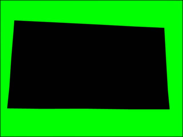
This part was very easy. I simply replaced (with a different color) the exact
same outlines in the Photoshop image that were just tweaked into perfect
alignment with the Convergence Mask. The outline selection areas were each
filled with black (000000) and the background with white (FFFFFF) or pure color.
Each individual black-filled outline and green background was then saved as a
jpeg. These were burned to DVD to become my actual burn masks. I tried using a
small amount of Gaussian blur (like up to 0.5 pixel) to soften the mask edges,
but I found that the projector defocusing was adequate in my case. This is what
one of the three final burn masks looks like:

Performing the CRT burn
The green CRT was electrically defocused to merge scan lines and diffuse the
spot energy a bit.
With everything warmed up, I used used the Convergence Mask DVD to recheck
alignment. Since the CRT was going to be run pretty hard, the phosphor area was
evenly warmed by gradually working up to a full white screen at full brightness
(by using contrast control) before hitting it with the bright mask image.
The actual mask DVD was put in the player, and final check of the mask
alignment was made. I used masking tape strips on the wall for reference, and I
would often make minor width, position, or even RGB point shift changes for a
quick correction, although the changes were never saved. I never ran my contrast
at 100%, since the drive seemed to flatten out at a lower setting.
Faint but detectable edges of wear began to appear on virgin phosphor within
5-6 hours or so, and the burn time to correct all 3 levels of the wear shown in
the photos was a little over 30 hours total. I had to change to my second level
burn mask after only about 9 hours. The point is that things can change pretty
fast if you are correcting for light wear, so you may want to do this only when
you can monitor the progress.
Many times along the way I would go back into Photoshop to make minor mask
changes. The left side of my CRT actually balanced out slightly before the right
side, probably due to the vertical keystone in the original setup. I replaced
the solid green mask background with a slight gradient from left to right (I
used 150 to 255 green and 200 to 255 at various times) to avoid over-wearing the
left side. I ran the green CRT with the masks until I could no longer detect the
original wear area on a projected solid color image, even with the tape lines to
guide me to where they were. The first time I displayed a white field, I was
ecstatic. There was absolutely no hint of a magenta tint in the center or any
lines at all. The wear pattern that was visible on the CRT face under normal
ambient light appears at first glance to be gone, but it is only because it has
been pushed out to within 4-6mm of the edge of the CRT face.
As a final step, a G2/white balance calibration was performed to calibrate
out the new (slightly subdued) tube output. It seemed to come out right where it
should be.
| Did you find this information useful? Please consider making a
donation to help defray the cost of managing and hosting future
articles, tips, and documents. |
|
|
|
Or
purchase
from
Amazon.com
and a small percentage automatically
goes to support this site at no extra cost to you! Visit their
Blu-ray and
4K UHD
stores for sales.
Want to show off your
home theater? See our
Blu-ray Release List & Must-Have Titles. |
|

|
|

|


