Definitive CRT Projector Setup Guide |
(Page 4)
|
Page:
1 2
3 4
5 6
|
| |
Linearity:
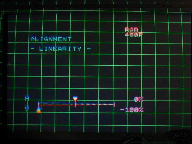
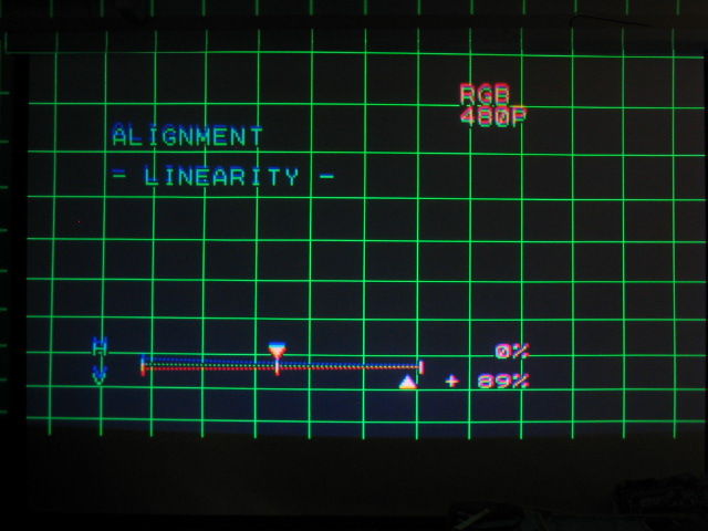
The LINEARITY control adjusts the size of the image between the top and the
bottom and the two sides. In other words, the top squares will change in size as
compared to the bottom ones. The Linearity function is used to compensate for
the amount of tilt of the projector. Here’s what the linearity control does:
(bottom squares are taller than the ones at the top)
And the opposite:
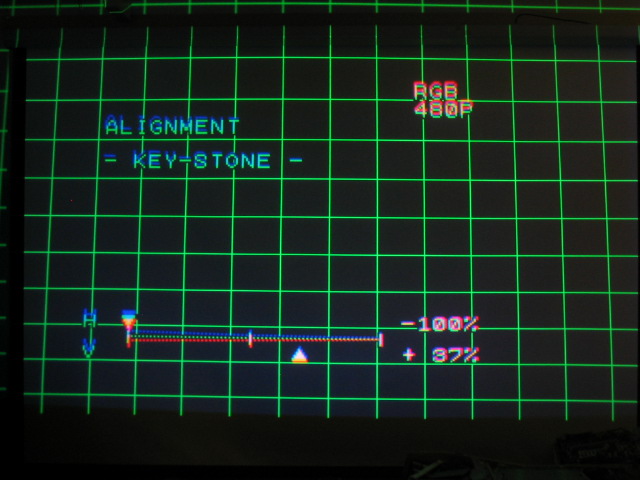
Keystone:
The keystone control adjusts how perpendicular the sides of the image are as
well as how straight the top and bottom of the image are. It’s completely normal
for a lot of keystone to be used to get the sides straight:
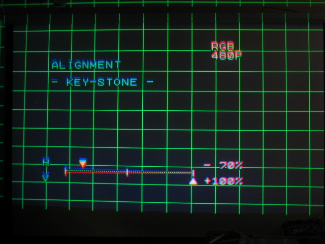
Too much side keystone correction:
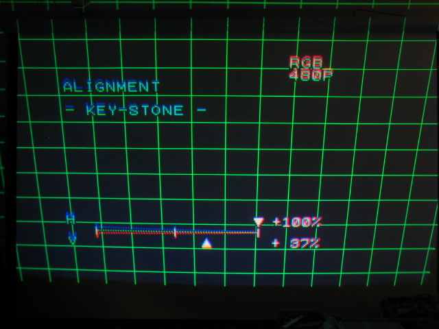
Not enough side keystone correction (top of image is tiled inwards, the
bottom of the image is wider than the top):
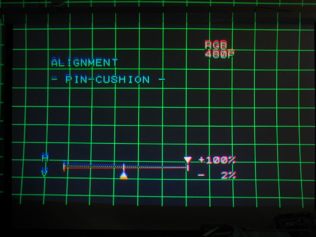
Pincushion:
The pincushion control is related to the keystone when you adjust the sides
and top/bottom of the image, but instead of the amount of tilt to the image, it
controls the amount of bending of the sides and top/bottom of the image. Here,
the sides of the image are bowed in at the middle.
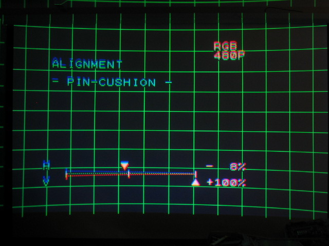
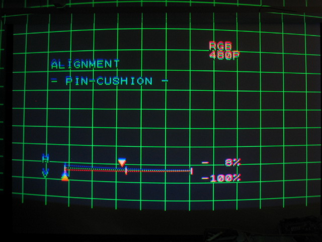
It’s more obvious in the top and bottom of the image as shown below:
Key and Pin Balance
Now pay attention! The following two controls/adjustments cause more
confusion and emails than any other settings on the NEC. (and you thought you’d
toughed it out so far!)
The balance controls for the key and pin controls balance out how much key
and pin are applied to the left and right (or top and bottom) of the image. To
access the ‘balance’ controls, simply press the ‘control’(ctrl) and then ‘key’
at the same time. This will bring up the ‘balance’ menu for key and pin. Press
the ‘key’ or ‘pin’ buttons once more to go back to the main control setting.
The balance controls will allow you to fine tune the key and pin controls for
better geometry. The picture below shows the imbalance that can be created when
the key balance is too far to one side.
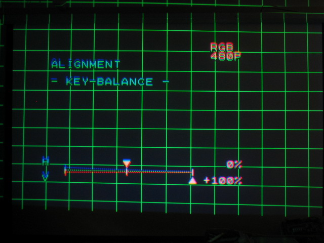
And
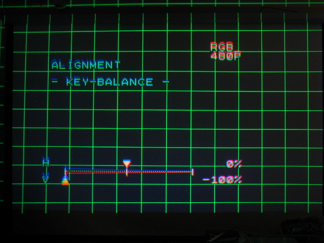
The pin balance control works in a similar fashion:
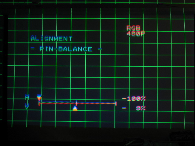
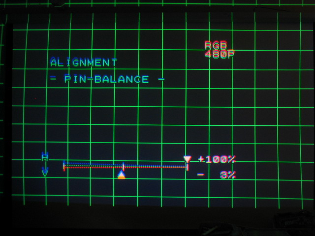
Point convergence
By adjusting all of the above parameters, you should be able to get decent
geometry out of the XG set… but it won’t be perfect. In order to obtain perfect
geometry out of the XG chassis, you MUST use some point convergence. Point
convergence comes stock on the NEC XG sets, and gives 100 points of fine tuning
per CRT. It cannot be overstated that point convergence cannot compensate for a
sloppy setup!
All of the above images were taken without the use of point convergence. You
can see in the best photo below that the geometry is pretty decent (for a 10
minute setup) that I used to take all of these images, but it’s not perfect.
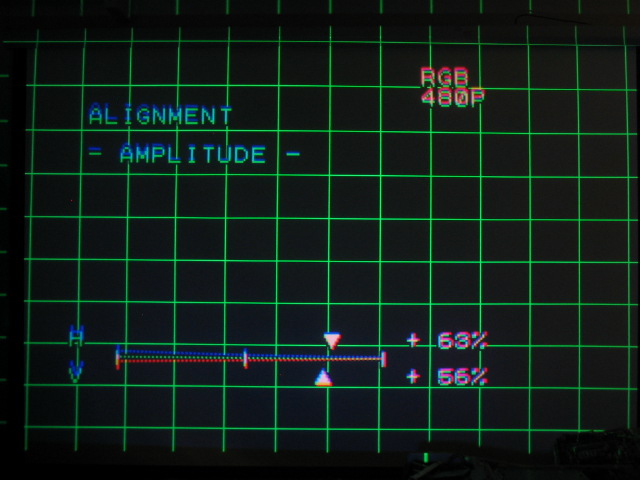
Once you get the image to look about as good as the one above, it’s time for
point convergence to really dial in the geometry. Depending on the software
version your XG has, you either have direct access to the 100 points of
convergence, or you have a selection of ‘coarse’, ‘medium’, or ‘fine’
convergence. Access each of the adjustments by simply pressing the ‘point’
button on the remote, and press ‘ctrl’ and ‘red’, ‘green’ or ‘blue’ at the same
time to toggle the point function between colors.
You can use up to approximately 10-15 clicks in any arrow direction for any
point location. If more point control is needed than 10-15 clicks in any
direction, the geometry adjustments are not close enough yet. Go back to the
beginning of this document and start over.
It’s a great idea to use string taped across the screen to ensure crosshatch
pattern line straightness. The point adjustment in ‘fine’ mode does the
following: (the picture shows point control of the red tube as compared to the
green).
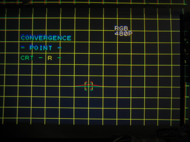
And
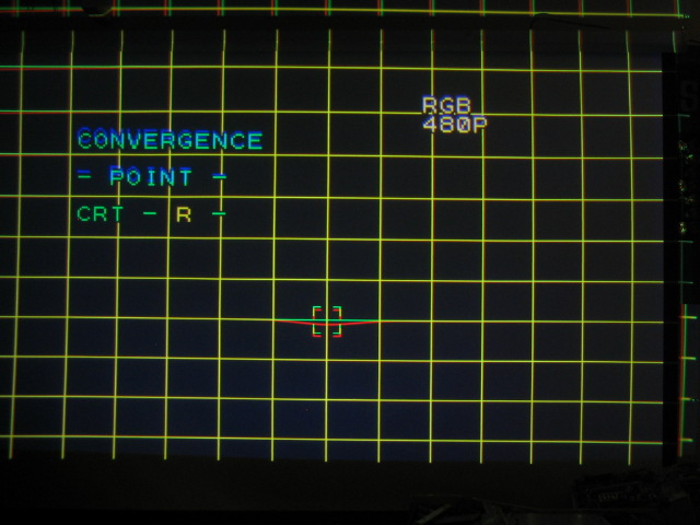
Once you’re happy with the green geometry, let’s start converging the red
tube over top of the green test pattern!

|


