4. VIM
There are three types of VIM boards:
• 50-2005-03P
• 50-2035-02P
• 50-2023-03P
The boards above are listed in chronological order. 50-2035-02P board is a
later version than 50-2005-03P. It has a wider bandwidth video chain. It also
has the blue gamma chip (U22) some of the early 8000 VIM’s did not have the
gamma circuit. There are several other technical differences, and they were
mostly added for higher scan rate use (super computer presentation), and may not
have any benefit for HT. Older boards use H1100 op-amps, but if you like the
high band go with the CLC449's.
Early version 8000's did not have the blue gamma circuit on the VIM. It was
included on all of the later models. That circuit is a simple op amp, and maybe
we can add it to the boards that does not have the circuit, I'm sure someone
could make that little circuit and make it available, it'll be quite easy to
install.
The same IC's on the neck board (U2) could be found on the VIM. You should
look for the same chips (CLC409, H1100, CLC449). The same upgrade applies here
on the VIM. The only difference would be that the CLC409 may not cause smearing
if on the VIM, you would more likely have a problem getting a very clean
resolution pattern, or the image would suffer from a weakness in detail, either
way, it could have a noticeable effect on the image. If the neck boards tested
ok, or have been corrected, you'll now need to perform a visual check for that
IC (CLC409) on the VIM, it's much easier to get to than the chips on the neck
boards.
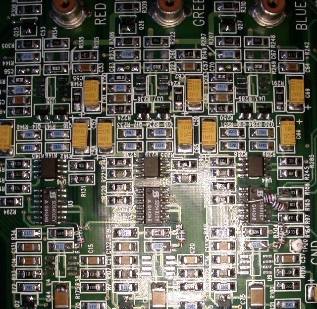
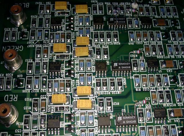
These pictures show the offending op-amps removed. U1, U4, U5, U35, U37 and
U42 and replaced with the new chips:


Next, you'll want to re-solder the mini RCA jack's on the PC board. And clean
both sides of the VIM with denatured alcohol and a tooth brush.
I'll throw in a mod:
The first thing that we'll do on this board (after the chip upgrade) is a Sync
Mod. This is the removal of the sync circuit from the green input (sync on
green), this is very important especially if using component to RGB conversion,
because that could cause TRI- level sync on the BNC's (composite sync on all
three BNC's). The problem that this could create is that you could have sync on
all five BNC's. That's not a problem for the Red and Blue, but by having this
signal on both the 'H' and 'V' BNC's to include the green BNC can confuse the
auto sync detect circuit that automatically detects what type of sync that's
being feed to the projector. The auto detect circuit looks for sync on the
following: separate sync on 'H' and 'V' BNC's, composite sync on green BNC,
composite sync on 'H' BNC. This circuit worked fine before component sync
conversion came along possibly placing sync on all five BNC's.
This is a simple fix, remove R152 (it should be located about 1" from the
blue relays) on the VIM module. By removing that resistor, you remove the sync
circuit from the green BNC. There is presently no present modern application for
sync on green (that I know of), especially for HT use.
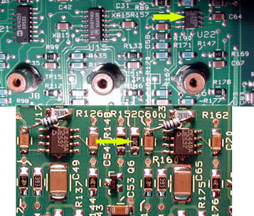
See the top part of the image below for a picture of a VIM. The upper part
shows "U22", but the RGB jacks are straight. This VIM is laid out different
compared to the previous VIM. This VIM has the gamma circuit.

The lower picture shows R152, this is the resistor to be removed to do away
with sync on green. Take the resistor (200 ohm with marking 201) out.

|


