5. Horizontal Deflection Module
This board is located between the green and blue tubes.
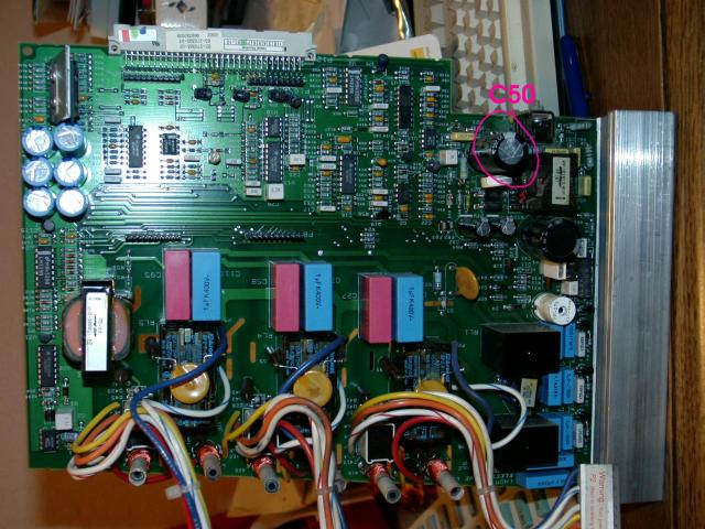
For this you'll need a good soldering tool, solder and a 220 mfd @ 160vdc cap
(C50). And remember that we clean each board as we go with denatured alcohol.

Replace "C50" it's in the modulator circuit on that board, The modulator
circuit supplies the operating voltages for the deflection power stage (power
MOSFETs), this circuit varies the voltage for the FETs based on the scan rate
that the project receives. If this cap leaks, it'll cause erratic width
performance, or inability to achieve max horizontal width.
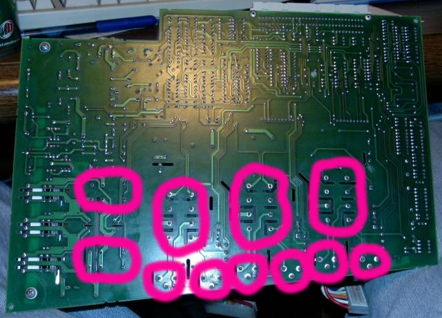
Then we'll move on to soldering various contacts on the board. If you remove
this board and closely examine the contacts you'll immediately notice the need
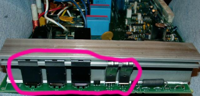
for soldering. The contacts that will need this soldering are the three power
MOSFETs and two transistors that are mounted to the heatsink:

The next items for soldering are the five relays and six coils that are
mounted next to the three large relays:

Next, inspect the three yoke connectors that are attached to the board, look
through the plastic connector and look for burns or dark marks in the area where
the contacts meet. If you see burn or darkness on that connector, it'll need
replacement.
This simple procedure greatly stabilizes this board, and it'll protect the
board from failure, because it's very important that these contacts are tightly
soldered, if not, as the board heats up, you could experience drifting or even
board failure.

|


