 |
||||||||||||
| Home |
|
Products For Sale |
FAQs, Tips, Manuals |
Referral List |
|
Photo Gallery |
|
Links |
|
Contact Us |
|
|
||||||||||||||||||
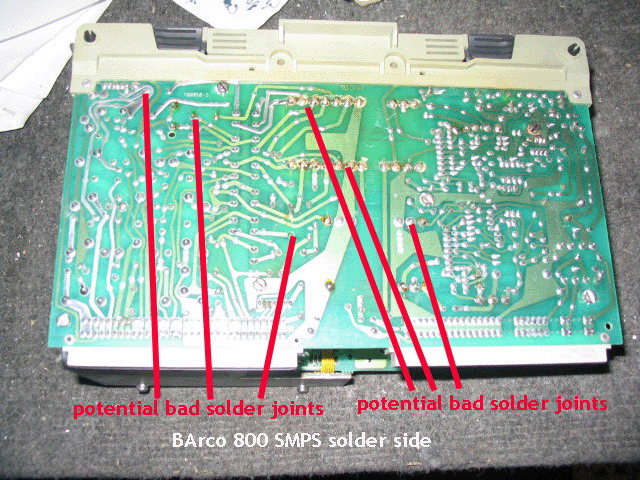
Out of all the parts in the projector, it's these power supplies that do fail the most as they are the hardest working part inside of the sets. The weak point on these supplies are the solder joints as shown below.
The above picture shows just a few of the weak solder joints that can crack over
time. If you have a good soldering hand, pull out this power supply and carefully
check all solder connections for cracks. The power transformer joints are very
suspect as are the ones on the fuse holders.
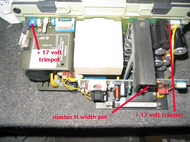
In order to have a proper operating set, the + 17 volt test point needs to be
set to 17 .0 volts, +/- 0.1 volt. This test point can shift in voltage over
time, so periodic checking of this test point is recommended.
|
|
|||||||||||||||||
© Copyright CurtPalme.com. All Rights Reserved. |


