 Barco 808/Cine8 Barco 808/Cine8
Layout and Setup Tips
|
(Page 5)
|
Page: 1 2
3 4 5 6
7 8
9 10 |
7) Switched Mode Power Supply (SMPS):

Also called the main power supply. There are
actually three power supplies on this board, the standby
one which is on all the time, and sends a low voltage to
the IR receivers, the internal keypad and the
controller board . the main power supply will turn on
when the standby or power button is pushed, and provides
power to all modules. The third supply supplies the H
deflection voltage to the horizontal board. This board
contains 9 fuses as per the photo.
The switch mode power
supply is one of the more common parts to fail in the Barco projectors. All circuits are driven by the power
supply, and the unit can run relatively warm.
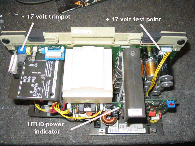
One adjustment that does drift occasionally is the + 17
volt trimpot. The test point for this trimpot is shown
in the picture. Use a meter to measure the DC voltage
with reference to the chassis, and adjust for + 17.0
volts*. This adjustment is critical for proper operation.
If the voltage is off by more than ½ volt, the picture
can blank out.
*Note: If you're reading through these 808 tips because
you have a 1208/1209 projector, be aware that the +17.0V
trimpot should actually be adjusted to 17.5V (not
17.0V). Setting the pot to 17.0V may cause eventual
spotburns.
The last point of interest is the green LED on the sub
power supply board. This LED shows that the HTHD power
supply section that drives the H output section is
working. You will not get a picture if this LED is out,
and the power supply must be sent for service.
The main power supply board actually contains two independent power
supplies. One drives the entire set, the second one provides the voltage
for the H output section and parts of the HV area. The set will not show
an image without all supplies working properly.
As per the first SMPS picture, the main 3 amp fuse is located to the
left of the supply, and if this fuse blows, the set will go dead.
Usually the fuse only blows if the SMPS has a problem in it, replace
this fuse ONCE only as a test, and if the second one blows, please
contact us for the repair.
To the right of the main board, you’ll find 7 additional fuses. Early
supplies had these fuses in fuse holders that look like the main 3 amp
fuse holder, the later power supplies have the fuses soldered into
place. These fuses do blow on occasion for no reason, again, if you have
a blown fuse as measured with a continuity tester, replace the fuse ONCE
only with an identical value, if the second one blows, the set has
problems. The soldered in fuses may be replaced with similar solderable
fuses. I use a type of fuse called a Picofuse. They look a bit different
than the originals, but serve the same function.
 s
s
|
|


 Barco 808/Cine8
