 |
||||||||||||
| Home |
|
Products For Sale |
FAQs, Tips, Manuals |
Referral List |
|
Photo Gallery |
|
Links |
|
Contact Us |
|
|
||||||||||||||||
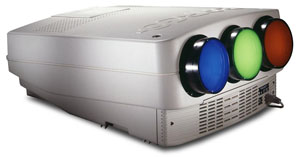
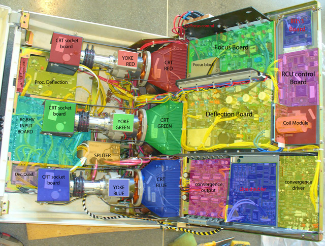
Barco 70x machines are a bit different from the other models of CRT projectors. While the circuits of the 70X series are loosely based on the Barco 800 and 801 series of sets, the layout is different, and very few parts are compatible with other Barco projectors. Note:
All LED’s in Barcos are color coded.
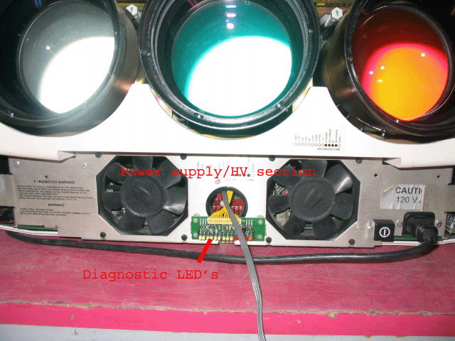
Internal layout of the 70x series Switch Mode Power supply and HV section Let’s start with the 70X series power supply board where a lot of failures occur. This power supply is located under the lenses behind the plastic cover. Remove the two Philips screws and take off the plastic cover. If the set has an IRIS on it, remove the wire going to the IRIS at the IRIS. The power supply will then pull out from the front. Note that there are a number of wires that connect the power supply to the rest of the set, and they can snag on the chassis when you pull out the supply. Unlike other Barcos, the HV supply, SMPS and AC input board are all located on this board. The circuits are similar in design to the 800/801 series, but the layout of the components is completely different from other Barco sets.
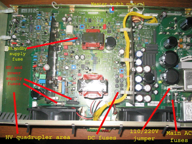
The above pictures are from a later model Barco 708 projector. The older sets had a single jumper wire in place of the 110/220 volt jumper. To set the older sets to 220V, simply cut the jumper wire on the board. For 110 operation, the jumper wire must be in place. There are a series of DC fuses in the unit. The older projectors had clip in fuses that were removed with needle-nose pliers from their fuse-holders. As with other Barco models, many of these fuses were sand filled (explosion-proof fuses) that have to be checked with a continuity tester. The later model sets as pictured above had these fuses soldered into place and are called Picofuses. These fuses are found at a good electronics parts store (Radio Shack won’t have them). There are two more fuses right behind the left fan. One is a 2 amp fuse that feeds the HV section, the 3 amp fuse is the main power supply. One last fuse is a 1/8 amp that feeds the standby power supply that powers the CPU board and the remote sensors. As with all fuses, replace the fuses with the correct value. If the fuse blows again, there’s a problem in the set. A larger value fuse will make whatever short is in the set worse. There are two fuses right behind the power cord inlet. These are the master power fuses, and do on occasion blow for no reason.
|
|
|||||||||||||||
© Copyright CurtPalme.com. All Rights Reserved. |

 Barco 70x/Cine7


