 |
||||||||||||
| Home |
|
Products For Sale |
FAQs, Tips, Manuals |
Referral List |
|
Photo Gallery |
|
Links |
|
Contact Us |
|
|
|||||||||||||||||
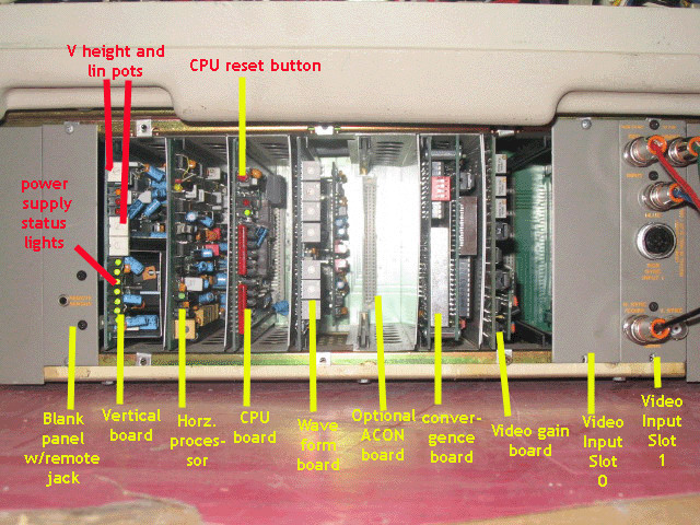
Looking under the back cover of the ECP projector, all models used the same board layout as shown below.
Upon holding the power button down for 2 seconds, the set powers up and the green power supply lights should all come on, indicating that all power supply voltages are present. The red lights on the H and V boards may come on momentarily, but should go out after the set goes through a number of self checks. Once the self checks test OK, the high voltage will crackle up, and the tubes should light up if an input signal is present. Starting from the left referring to the above image, the blank panel only houses an 1/8” mini jack so that a wired service remote may access the projector. This is useful for doing close screen convergence, when the projector is used in a rear projection mode or if the projector is far away from the screen. The first PC board with the green lights on it is the vertical output board. It provides the vertical sync and output, and has the master height and linearity controls on it. An H and V scan fail light are also on this board. The second board is the horizontal processor. This board has the horizontal driver and sync sections of the set on it, and those signals then drive the H deflection boards that are located under each tube. The third board is the CPU board that has the main microprocessor, the Dallas chip and the master reset button on it. The fourth board is the waveform board that generates the convergence waveforms for the convergence board on it. The 5th slot is usually empty, reserved for the ACON or automatic convergence board. If the ECP model is designated as an ‘01’, ie. 4101, 3501, etc, then the set originally came from Electrohome with the ACON board and camera installed. Some people remove the ACON hardware, it’s easy to install onto sets that did not come stock from the factory with it. The sixth board is the main convergence board. This board controls the convergence parameters for all three tubes. The seventh slot is the video gain board. This controls the amount of R G and B signals going to each video output board located on the back of each CRT. The eighth slot (shown here as a blank) is designated as Slot 0, the first video input board. Each ECP has the ability to accept two video input boards that came in a number of configurations, either video, S-video or RGB. Most boards were dual input , so with two input boards, you had available a total of 4 video inputs, eliminating the need for an external video switcher. Neat, huh?!? The ninth slot was the second video input card, designated as SLOT 1. When pressing the remote input selection, you select which slot you want to use, then which input on that particular slot. So ‘Source’ ‘0’,’1’ selected the first input on slot 0. ‘Source’ ‘1’,’2’ would select input 2 on slot 1. THE picture above shows a common dual RGB input board. Input 1 is a unique Electrohome 10 pin connector, and the matching plug is hard to find. Input 2 is a 5 BNC standard RGB input that accepts RGsB, RGBS or RGBHV signals.
|
|
||||||||||||||||
© Copyright CurtPalme.com. All Rights Reserved. |

 Electrohome ECP Series
