 |
||||||||||||
| Home |
|
Products For Sale |
FAQs, Tips, Manuals |
Referral List |
|
Photo Gallery |
|
Links |
|
Contact Us |
|
|
||||||||||||||||||
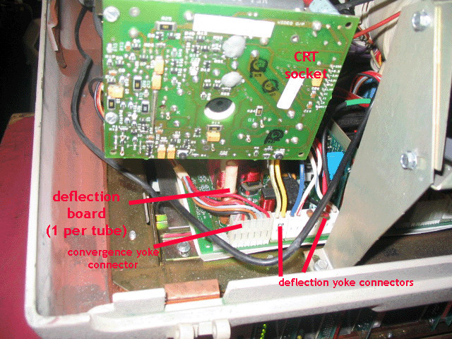
The below image shows one of the CRT output sockets. These pull right off the back of the tube, and all connectors pull off the board. Note that there are three single pin connectors right beside each other on the component side of the board with the exception of the focusing wire that pulls off the back of the focusing board. Ensure that the two black wires go back onto the right pins, and that the G2 wire goes to the third pin. Sparks may result if these wires are incorrectly installed.
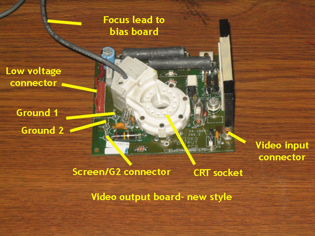
All three CRT sockets are identical, so if problems occur with one color, these CRT boards may be swapped around to eliminate them as a source of the problem (or to confirm it.). Here’s a front view of the CRT socket.
The front of the CRT sockets have several connectors that need to be unplugged if servicing or swapping boards. There are two ground connectors for two black ground wires. It does not matter which connector goes where. The G2/screen connector should not be mixed up with the ground screws. The above image shows the newer style of CRT output board, used in late model ECP 3100/4100’s and the ECP 3500 and 4500. These use a mini RCA connector for the video input feed, the older style used a larger two pin connector.
|
|
|||||||||||||||||
© Copyright CurtPalme.com. All Rights Reserved. |

 Electrohome ECP Series

