 |
||||||||||||
| Home |
|
Products For Sale |
FAQs, Tips, Manuals |
Referral List |
|
Photo Gallery |
|
Links |
|
Contact Us |
|
|
|||||||||||||||||
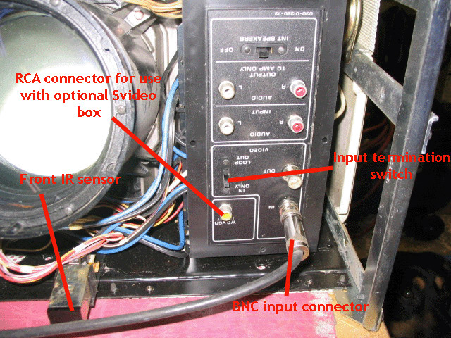
Note: The module connectors are clearly labelled, but it’s all too easy to inadvertently interchange module connectors. If you interchange the two 4 pin module connectors on the HV board for example, you will blow the HV board and the one of the power supply boards. If you’re going to swap out boards, be very careful in connecting the module plugs to the correct location on the board. Input connector board Let’s start with the outside of the set that is very confusing to newbie PRO 851 owners. Most of the Zenith sets are the PRO 851 which is a video only set. The set has no internal tuner, and needs a video signal from a video source fed into the BNC input connectors. Many people email or call me saying that they can’t get a picture when they feed a video signal into the yellow RCA connector on the front panel shown below:
The yellow RCA connector is only used in conjunction with the optional external S-video box that Zenith made a very limited number of. You won’t get anything out of the projector by connecting to the yellow RCA connector. The video input needs to go to the BNC connector as shown. The input termination switch needs to be left on the ‘in only’ position. When the switch is put in the ‘loop out’ position, you will get a brighter but a washed out image. Occasionally this switch will corrode resulting in a washed out picture. This switch will clean up when control cleaner is shot into the switch. If the set you’re using is installed in a sports bar, turn the internal speaker switch to the ‘off’ position. The internal audio amp can pick up stray cell phone signals, resulting in a loud buzz if a customer within 10’ of the projector is using a cell phone. I’ve had many calls over the years from local sports bars that say the ‘set is buzzing’, only to find that it’s a cell phone causing the buzz through the speakers.
|
|
||||||||||||||||
© Copyright CurtPalme.com. All Rights Reserved. |

 Zenith PRO 841x/851x
