 |
||||||||||||
| Home |
|
Products For Sale |
FAQs, Tips, Manuals |
Referral List |
|
Photo Gallery |
|
Links |
|
Contact Us |
|
|
||||||||||||||||||
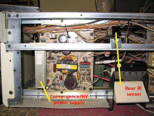
Chassis When you take off the back of the set, you’ll see two boards under the cover. The left board is the HV and convergence power supply. This board has no user adjustments on it. Some of these boards were poorly assembled by Zenith, and a short on this board will instantly blow the main fuse on the power supply board. The rear IR sensor is only on the latest PRO 851 models, there was only a front IR sensor on earlier sets.
Under the rear IR sensor is the connection for the AC cord. A fuse holder is also located on this small panel, but the fuse on the main power supply usually will blow before the chassis fuse will.
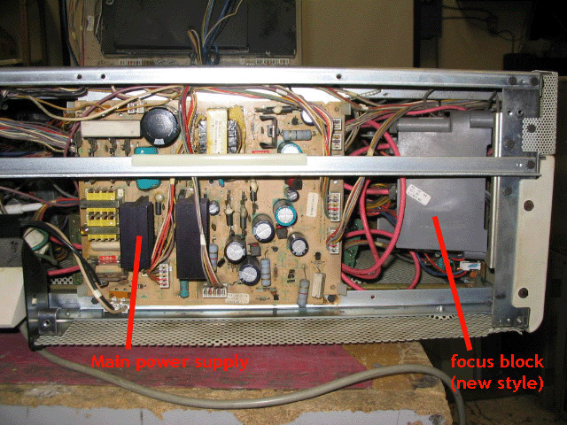
The main power supply has one +128 volt trimpot on it, but under normal use, this trimpot will never require adjustment. This board is usually fairly reliable, and will only blow due to another dead short in the set, or improper connection of module connectors. To the right of the main power supply is the focus block. As stated elsewhere in this Zenith tips section, the original one piece focus blocks were notorious for overheating and causing fluctuating brightness, shifting focus and intermittent shutdown of the set. This picture shows the new two piece focus block that is much more reliable. The focus and G2 connectors end up being mounted under the top cover.
|
|
|||||||||||||||||
© Copyright CurtPalme.com. All Rights Reserved. |

 Zenith PRO 841x/851x

