 |
||||||||||||
| Home |
|
Products For Sale |
FAQs, Tips, Manuals |
Referral List |
|
Photo Gallery |
|
Links |
|
Contact Us |
|
|
||||||||||||||||||
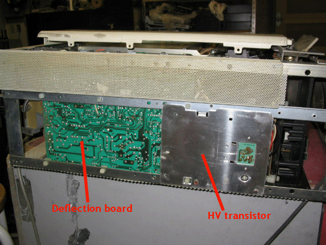
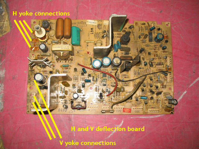
Side View When you take the side panel off of the side of the set, you expose the back of the deflection board and the transistor that works in conjunction with the HV board. The deflection board contains all of the horizontal and vertical output components. There are no user adjustments on the deflection board, but there is one fuse on the edge of the board that is soldered into place. It rarely blows unless there’s a fault on the deflection board or a module connector is installed incorrectly.
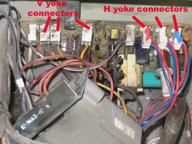
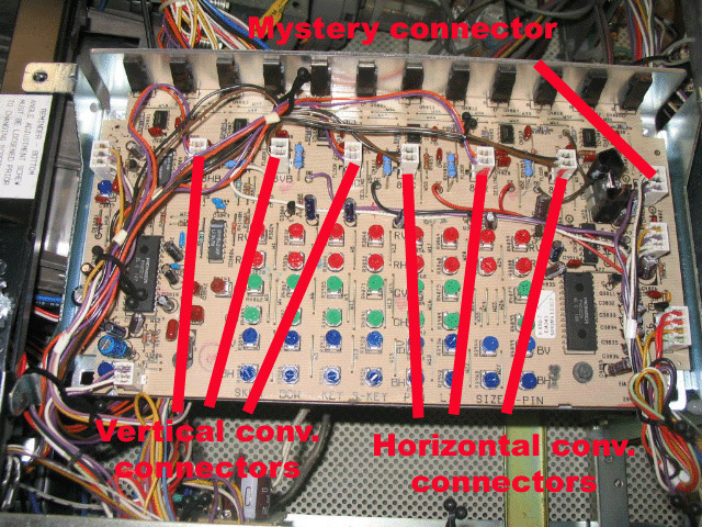
The 6 yoke connectors are shown below. There is a ‘floor’ and ‘ceiling’ position stamped on the board, and these connectors must be oriented the right way for floor or ceiling projection. There are also six connectors on the convergence board that must be correctly oriented as well for good convergence control and geometry of all colors.
Looking at the deflection board when moving the focus block aside, the deflection yoke connectors can be changed without taking the deflection board out of the set:
There are 6 connectors on the convergence board that need to be changed when switching the Zenith projector from floor to ceiling or vice versa:
There is also a 7th connector that was never really properly described in the Zenith literature as indicated in the above drawing. It chances the range of the convergence controls, so if you run out of range of a particular adjustment, try pulling this 7th connector out and reversing it to see if you get better range of the various controls. There are a few unmarked controls on the convergence board. These are best left alone as they need test equipment to properly set them. Under normal use, these controls do not need adjusting.
|
|
|||||||||||||||||
© Copyright CurtPalme.com. All Rights Reserved. |

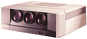 Zenith PRO 841x/851x
