 |
||||||||||||
| Home |
|
Products For Sale |
FAQs, Tips, Manuals |
Referral List |
|
Photo Gallery |
|
Links |
|
Contact Us |
|
|
|||||||||||||||||||||||||
Controller board
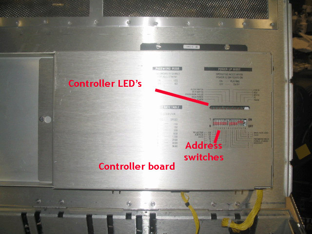
This is the main CPU board that controls all of the functions of the Barco projector, and it also houses the memory chips for convergence and other parameters stored in memory. The metal cover slides off to expose the CPU board with the screw shown on the left. Generally this board is very reliable, and does not need normal service. LED’s- There are a number of LED’s on the controller board. They don’t actually tell us too much about troubleshooting a Barco, but will give us some information about how the set is working. When the set is in the standby mode (not on, but powered up), the standby power light will be on, along with the processor light that will be flashing rapidly. This is normal, and indicates that the CPU is working. At power-up, the main and standby power lights will come on, you’ll hear the SMPS power up, and the processor light will eventually go back to flashing. Assuming that all is well within the set, the set will stay powered up and you’ll get an image. The ‘block match’ light means that the input signal has locked to an internal memory location that has been previously set up. If the set has a fault in it, the set may never power-up when the standby button is pressed, and the error light on the controller board will flash very slowly. The set will continue to try to power up for about 10 seconds, and then will go back to the standby mode. If the set does not power up at all, but will stay in the standby mode, then the main SMPS is usually at fault. If the set powers up but shuts down again after a few seconds, there is some fault in the set that is causing the set to shut down. If the set is dead completely with no processor light flashing, then the SMPS has usually failed. Note that the controller board runs on the 5 volt standby supply that is live as soon as the projector is plugged in. If the controller board does not get the 5 volts from the standby supply, the set will be dead. The 5 volt standby supply does power several other boards in the set, so a short elsewhere in the set will also cause the projector to be completely dead, even if the SMPS is working fine. A short on any power supply rail will cause the SMPS to be dead without blowing fuses. DIP switches- controller board There are two sets of 8 DIP switches on the controller board. The left 8 switches set the projector address location, This is used with multiple projector installs, so that one software program or one remote can access up to 128 projectors independently. For proper operation, it’s good to set the projector address to 0. The right set of DIP switches serve several functions as outlined on the metal cover. The first three switches are reserved, leave these alone. These are for some super secret internal Barco function that I know nothing about. The 4th switch allows the set to power up as soon as AC power is supplied. This is handy if you want to control the main power function to the projector by simply applying power to the set without using the remote. The 5th switch turns the password on and off. A lot of surplus projectors come with this switch turned on, slide it to the off position and you’ll get full access to the service and convergence menus without ever knowing what password was programmed into the set by the last owner. The last three switches set the baud rate that are used by the computer port to talk to a remote computer.
|
|
||||||||||||||||||||||||
© Copyright CurtPalme.com. All Rights Reserved. |

 Barco 120x/Cine9

