 |
||||||||||||
| Home |
|
Products For Sale |
FAQs, Tips, Manuals |
Referral List |
|
Photo Gallery |
|
Links |
|
Contact Us |
|
|
|||||||||||||||||
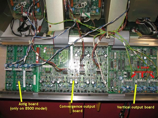
Rear Heatsink Below is the view of the inside of the heatsink assembly. It shows the three individual boards (note that the convergence output and V output boards are connected together, but a sharp X-acto knife will cut the joining areas). Two screws form the hinge points for this large heatsink, and one outer plastic case side has to be removed to access those screws. Once one of the screws is loosened, the heatsink will slide off the hinge screw on the other end of the heatsink. Note to use caution if removing the heatsink while the set is on the ceiling. The assembly weighs about 10 lbs and if you’re not ready for the weight, it can fall to the ground, not to mention the possibility of giving you a good size cut on your noggin.
The astig and convergence connectors can only be plugged in one way, the V output connectors however can be inserted either way on the board pins. This allows you to flip the image depending on how the projector is mounted. There are two flat ribbon cables connecting the V and convergence boards to the motherboard in the set. Make sure that the right ribbon cable is used for the right board as the two ribbon cable ends that plug into the motherboard are different. Fortunately the motherboard connector is stamped as to whether it’s for the C or V board! There are no user adjustable controls on any of these boards. Failure of the C and V boards can occur if the connecting cables get pinched in the case frame (it can happen if you’re not careful when closing the case after a routine service). If the V fail light comes on, there’s a good chance that the V board section has failed. If you lose the ability to converge a color in either a N-S or E-W direction, chances are that a section on the C board has failed. I strongly recommend that you send the whole heatsink assembly in for service, as the output transistors can easily be damaged in shipping if you remove the PC boards from the heatsink. Note also that the C board controls the various zones of convergence for all three colors. The master H and V shift for each color (the zone in the middle of each color) is actually controlled by the H output board. If you lose the ability to do a master H or V shift for any or all colors, the fault is usually on the H output board.
|
|
||||||||||||||||
© Copyright CurtPalme.com. All Rights Reserved. |

 Electrohome Marquee
Series