G70 C block PCB update to use P16LJE07/06 tubes
Okay, here is the optional last part of the job: A C block PCB update in case
you want to use Panasonic P16LJE07 or P16LJE06 tubes instead of the original
Sony provided P16LJE08 tubes.
It’s true that it can be easier (and cheaper) to find P16LJE07 or P16LJE06
tubes rather than ’08. With a small C-Block Sony PCB update, the G70 can use
these new tubes with great success!
- First part of this update is to relocate the G1 pin connection on the PCB
- Second part is KH grid connection to ground to be done through 4.7Mohms 1/2W
resistance
Thanks to Azzad, Terry and Mark for their help on this part.
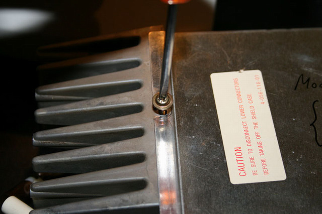
1. After disconnecting all the relevant C block incoming cables, take the C
block out of the G70 unit. Unscrew its heatsink top screw and gently slide up
the back PCB shield/cover:
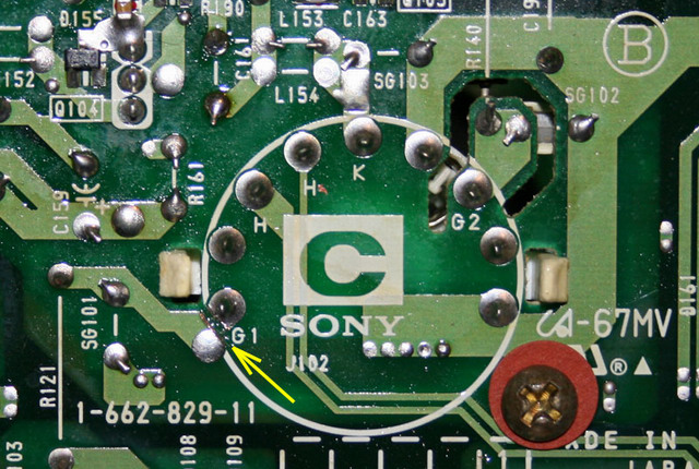
2. Locate the G1 pad and cut the incoming PCB track using a sharp
cutter/blade. Do not damage the circular G1 PCB pad:
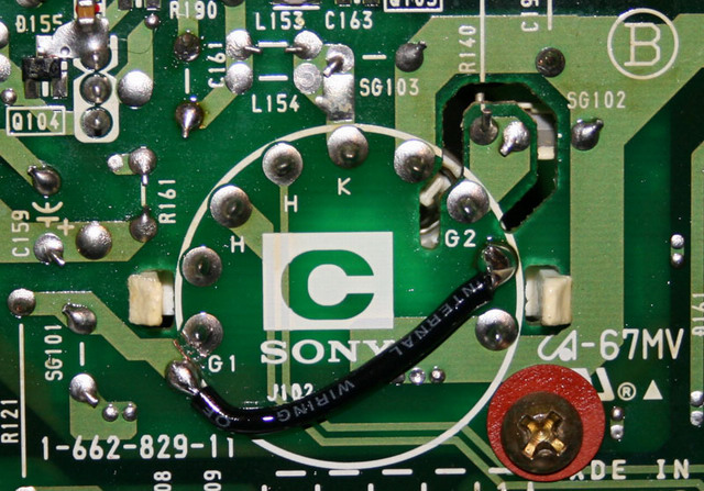
3. Using a small length insulated wire, connect it to both locations using
solder:
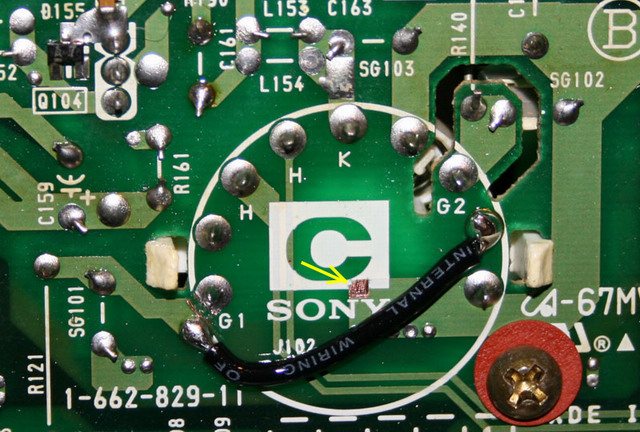
4. Remove a 2x2mm area of copper varnish on the ground copper area track
location using a sharp cutter/blade:
5. Solder two 10Mohms 1/4W resistors leads this way on ground track end.
Clean the old G1/NC pads from solder (yellow arrows):
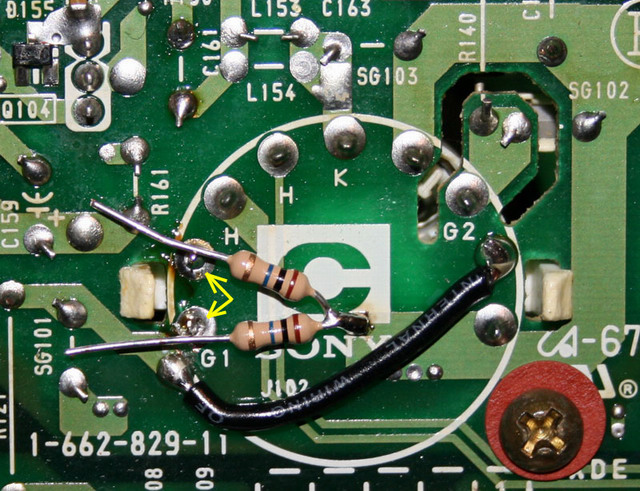
6. Bend the two 10Mohms 1/4W resistors other ends together around the old
G1/NC socket pins:
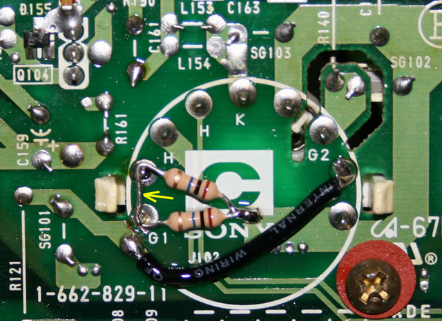
7. Solder the two 10Mohms 1/4W resistor ends together around the old G1/NC
socket pins:
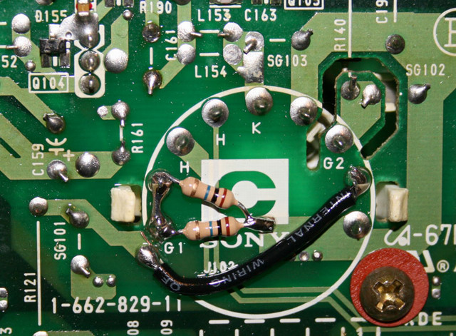
Important : Clean the PCB surface from solder flux/resin since there is HV
potentials applied to these pins!
It’s done, now the C block is compatible with P16LJE07 or P16LJE06 tubes!
| Did you find this information useful? Please consider making a
donation to help defray the cost of managing and hosting future
articles, tips, and documents. |
|
|
|
Or
purchase
from
Amazon.com
and a small percentage automatically
goes to support this site at no extra cost to you! Visit their
Blu-ray and
4K UHD
stores for sales.
Want to show off your
home theater? See our
Blu-ray Release List & Must-Have Titles. |
|

|
|

|


