27. Now, carefully slide-in the complete assembly within the G70 unit, with
one hand on LC housing and the other on the tube neck end. Check that every
wire/connector is NOT stressed during this operation. Ensure that the HV lead
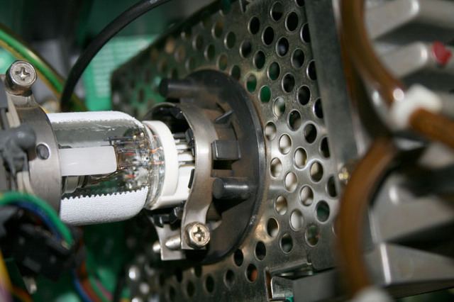
comes in the right conduit. Then reconnect the C block to the tube neck.
Ensure that the pins are well inserted within the C block tube’s socket by
looking through the C block front grid holes. Then secure the neck screw:
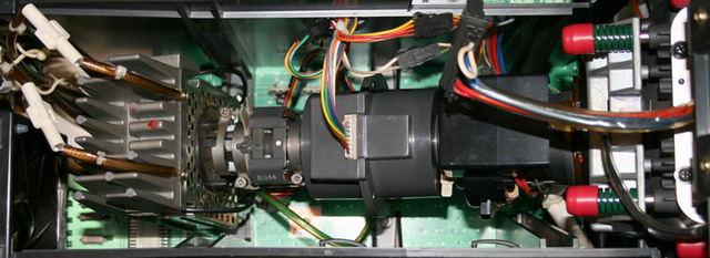
28. Re-connect all of the tubes relevant coils wires/connectors. Do not forget
to re-connect the HV lead end to the HV block:
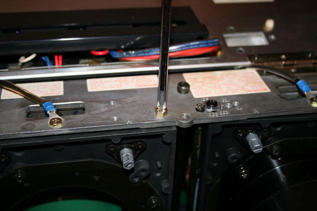
29. Screw back in place all of the tube’s LC housing top screws (two long black
screws and two short gold screws):
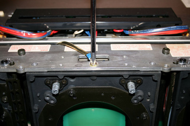
30. Screw back in place the top tube rotation screw with the chassis ground
lead:
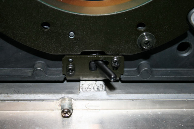
31. Slide the bottom rotation tube axis left and down:
32. Open your G70 service manual in section 3 (adjustments) and redo section
1.3.1 to 1.3.11 adjustments for the relevant (new) tube(s). This will takes
around four hours to do all these necessary adjustments.
Also use a thick rubber glove to manipulate the coils during section 3 of the
Service manual adjustments since there is around 150V on the DY/sub-DY coils.
That’s all for the tube replacement procedure. The next page describes
the C block PCB update in case you wish to use Panasonic P16LJE07 or P16LJE06
tubes instead of the original Sony provided P16LJE08 tubes.

|


